Engineering Tolerances: Dimensional, GD&T and Fits
In engineering and manufacturing, tolerances are very important. They help create parts that fit within the limits set. This also ensures that the final product works correctly.
This article will explain engineering tolerances. It will cover four main topics: dimensional tolerances, geometric dimensioning and tolerancing (GD&T), surface finish tolerances, and fits. We will discuss why they matter, how they are used, and their effects on the manufacturing process.
Table of Contents
Dimensional Tolerances
Definition and Importance
Dimensional tolerances are a critical subset of engineering tolerances. They specify the allowable variations in the size of a part. For example, if a part is 100 mm long with a tolerance of ±0.1 mm, it can be between 99.9 mm and 100.1 mm long.
Engineering tolerances, especially dimensional tolerances, are important. They decide how closely a part must match its specified size. If the tolerance is too tight, it can raise manufacturing costs and make it hard to get the right precision. On the other hand, if the tolerance is too loose, the parts may not fit or work properly.
Types of Dimensional Tolerances
There are several ways to specify dimensional tolerances within the broader framework of engineering tolerances:
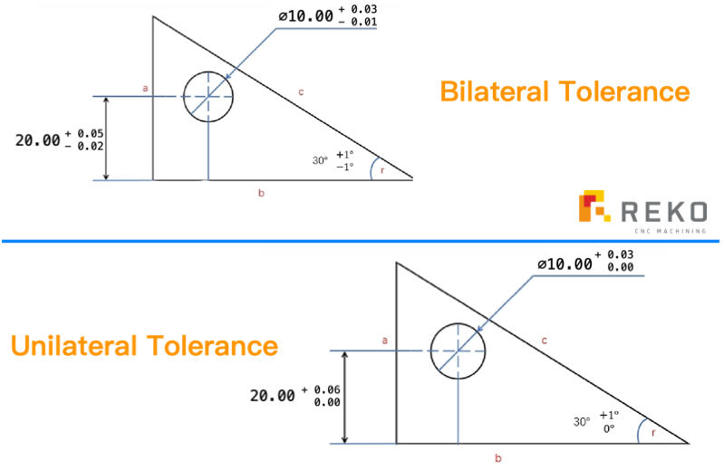
1. Bilateral Tolerance: This type of tolerance allows variation in both directions from the nominal dimension. For example, a dimension of 50 mm ±0.5 mm means the part can be between 49.5 mm and 50.5 mm.
2. Unilateral Tolerance: Unilateral tolerances allow variation in only one direction. For instance, a dimension of 50 mm +0.5 mm/-0 mm means the part can be between 50 mm and 50.5 mm.
3. Limit Dimensions: The specifications include a minimum and maximum dimension. For example, someone might specify a dimension as 50 mm min to 51 mm max.
Factors Influencing Dimensional Tolerance
Several factors influence the choice of dimensional tolerance within the scope of engineering tolerances:
· Functionality: The primary consideration is the function of the part. If a part needs to fit precisely with another, tighter tolerances may be required.
· Material Properties: Different materials have different manufacturing capabilities. For example, plastic parts may have wider tolerances compared to metal parts due to differences in manufacturing processes.
· Manufacturing Process: The precision of the manufacturing process also affects tolerance selection. Processes like CNC machining can achieve tighter tolerances compared to casting or forging.
· Cost: Tighter tolerances generally increase manufacturing costs. Therefore, a balance must be struck between precision and affordability.
Tolerance Calculation Methods
Tolerance tables are commonly used in engineering to quickly determine the appropriate tolerance for a given
dimension. These tables are based on standard practices and industry norms. For example, the ISO (International
Organization for Standardization) provides standard tolerance grades that users can apply to different dimensions
| Nominal size | IT1 | IT2 | IT3 | IT4 | IT5 | IT6 | IT7 | IT8 | IT9 | IT10 | IT11 | IT12 | IT13 | IT14 | IT15 | IT16 | IT17 | IT18 | |
|---|---|---|---|---|---|---|---|---|---|---|---|---|---|---|---|---|---|---|---|
| From | To | μm | mm | ||||||||||||||||
| 1 | 3 | 0.8 | 1.2 | 2 | 3 | 4 | 6 | 10 | 14 | 25 | 40 | 60 | 0.1 | 0.14 | 0.25 | 0.4 | 0.6 | 1 | 1.4 |
| 3 | 6 | 1 | 1.5 | 2.5 | 4 | 5 | 8 | 12 | 18 | 30 | 48 | 75 | 0.12 | 0.18 | 0.3 | 0.48 | 0.75 | 1.2 | 1.8 |
| 6 | 10 | 1 | 1.5 | 2.5 | 4 | 6 | 9 | 15 | 22 | 36 | 58 | 90 | 0.15 | 0.22 | 0.36 | 0.58 | 0.9 | 1.5 | 2.2 |
| 10 | 18 | 1.2 | 2 | 3 | 5 | 8 | 11 | 18 | 27 | 43 | 70 | 110 | 0.18 | 0.27 | 0.43 | 0.7 | 1.1 | 1.8 | 2.7 |
| 18 | 30 | 1.5 | 2.5 | 4 | 6 | 9 | 13 | 21 | 33 | 52 | 84 | 130 | 0.21 | 0.33 | 0.52 | 0.84 | 1.3 | 2.1 | 3.3 |
| 30 | 50 | 1.5 | 2.5 | 4 | 7 | 11 | 16 | 25 | 39 | 62 | 100 | 160 | 0.25 | 0.39 | 0.62 | 1 | 1.6 | 2.5 | 3.9 |
| 50 | 80 | 2 | 3 | 5 | 8 | 13 | 19 | 30 | 46 | 74 | 120 | 190 | 0.3 | 0.46 | 0.74 | 1.2 | 1.9 | 3 | 4.6 |
| 80 | 120 | 2.5 | 4 | 6 | 10 | 15 | 22 | 35 | 54 | 87 | 140 | 220 | 0.35 | 0.54 | 0.87 | 1.4 | 2.2 | 3.5 | 5.4 |
| 120 | 180 | 3.5 | 5 | 8 | 12 | 18 | 25 | 40 | 63 | 100 | 160 | 250 | 0.4 | 0.63 | 1 | 1.6 | 2.5 | 4 | 6.3 |
| 180 | 250 | 4.5 | 7 | 10 | 14 | 20 | 29 | 46 | 72 | 115 | 185 | 290 | 0.46 | 0.72 | 1.15 | 1.85 | 2.9 | 4.6 | 7.2 |
| 250 | 315 | 6 | 8 | 12 | 16 | 23 | 32 | 52 | 81 | 130 | 210 | 320 | 0.52 | 0.81 | 1.3 | 2.1 | 3.2 | 5.2 | 8.1 |
| 315 | 400 | 7 | 9 | 13 | 18 | 25 | 36 | 57 | 89 | 140 | 230 | 360 | 0.57 | 0.89 | 1.4 | 2.3 | 3.6 | 5.7 | 8.9 |
| 400 | 500 | 8 | 10 | 15 | 20 | 27 | 40 | 63 | 97 | 155 | 250 | 400 | 0.63 | 0.97 | 1.55 | 2.5 | 4 | 6.3 | 9.7 |
| 500 | 630 | 9 | 11 | 16 | 22 | 32 | 44 | 70 | 110 | 175 | 280 | 440 | 0.7 | 1.1 | 1.75 | 2.8 | 4.4 | 7 | 11 |
| 630 | 800 | 10 | 13 | 18 | 25 | 36 | 50 | 80 | 125 | 200 | 320 | 500 | 0.8 | 1.25 | 2 | 3.2 | 5 | 8 | 12.5 |
| 800 | 1000 | 11 | 15 | 21 | 28 | 40 | 56 | 90 | 140 | 230 | 360 | 560 | 0.9 | 1.4 | 2.3 | 3.6 | 5.6 | 9 | 14 |
| 1000 | 1250 | 13 | 18 | 24 | 33 | 47 | 66 | 105 | 165 | 260 | 420 | 660 | 1.05 | 1.65 | 2.6 | 4.2 | 6.6 | 10.5 | 16.5 |
| 1250 | 1600 | 15 | 21 | 29 | 39 | 55 | 78 | 125 | 195 | 310 | 500 | 780 | 1.25 | 1.95 | 3.1 | 5 | 7.8 | 12.5 | 19.5 |
| 1600 | 2000 | 18 | 25 | 35 | 46 | 65 | 92 | 150 | 230 | 370 | 600 | 920 | 1.5 | 2.3 | 3.7 | 6 | 9.2 | 15 | 23 |
| 2000 | 2500 | 22 | 30 | 41 | 55 | 78 | 110 | 175 | 280 | 440 | 700 | 1100 | 1.75 | 2.8 | 4.4 | 7 | 11 | 17.5 | 28 |
| 2500 | 3150 | 26 | 36 | 50 | 68 | 96 | 135 | 210 | 330 | 540 | 860 | 1350 | 2.1 | 3.3 | 5.4 | 8.6 | 13.5 | 21 | 33 |
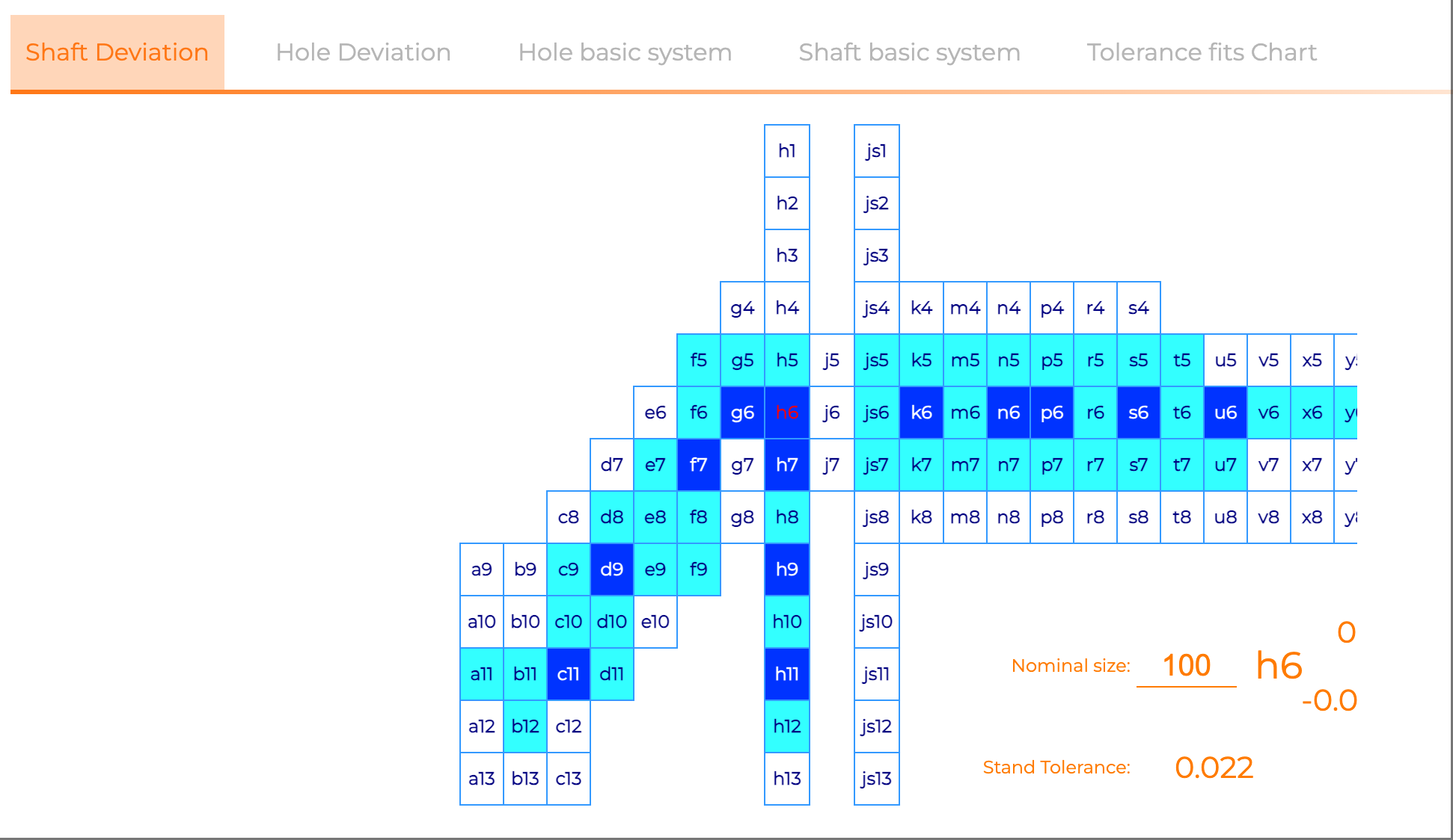
We have designed calculators for Shaft Deviation, Hole Deviation, Hole Basic System, Shaft Basic System, and Tolerance Fits Chart based on the Standard Tolerance Table. These tools can serve as auxiliary aids for designers to look up tolerances in their daily work.
Geometric Dimensioning and Tolerancing (GD&T)
Overview of GD&T
Geometric Dimensioning and Tolerancing (GD&T) is used to define the nominal (theoretically perfect) geometry of parts and assemblies, the allowable variation in size, form, orientation, and location of individual features, and how features may vary in relation to one another such that a component is considered satisfactory for its intended use.
GD&T is an important part of engineering tolerances. It offers a standard way to define and control the shape of mechanical parts.
Benefits of GD&T
1. Improved Communication: GD&T provides a standardized language for engineers, designers, and manufacturers to communicate the design intent clearly. This reduces misunderstandings and errors.
2. Improved Accuracy: By setting tolerances for shapes, GD&T makes sure parts fit together well. This boosts the quality and performance of the final product.
3. Cost Efficiency: While GD&T can seem complex, it often leads to cost savings by reducing the need for rework and scrap. By clearly defining the acceptable variations, it helps manufacturers produce parts that meet the design requirements more consistently.
4. Improved Functionality: GD&T looks at how the part needs to work. It makes sure the part functions well in the final assembly. This is particularly important in industries where precision is critical, such as aerospace and medical devices.
Key GD&T Symbols and Concepts
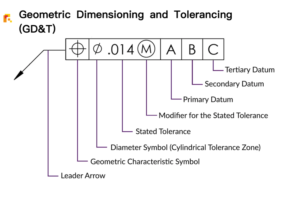
1. Datums: Datums are reference points, lines, or planes used to establish a coordinate system for the part. They are essential for defining the locati0n and orientation of other features.
2. Form Tolerances: These include flatness, straightness, circularity, and cylindricity. They control the shape of individual features.
3. Profile Tolerances: These control the shape of a surface or a line relative to a theoretical perfect shape. You can apply profile tolerances to both individual features and the overall shape of a part.
4. Orientation Tolerances: These include perpendicularity, parallelism, and angularity. They control the orientation of one feature relative to another.
5. Location Tolerances: Position is the most common location tolerance. It controls where a feature is in relation to a datum system.
6. Runout and Concentricity: These tolerances control the relationship between rotating parts and their axes.
Surface Finish Tolerances
Definition and Importance
Surface finish, also known as surface texture, refers to the roughness or smoothness of a part's surface. Surface finish tolerances specify the acceptable range of roughness for a given surface. These tolerances are critical because the surface finish can affect the part's functionality, appearance, and durability.
Types of Surface Finish Tolerances
Surface finish tolerances are typically specified using parameters such as:
1. Roughness Average (Ra): This is the most common measure. It shows the average of the surface profile's deviations from the mean line.
2. Roughness Maximum Height (Rz): This parameter represents the maximum height of the surface profile.
3. Roughness Total (Rt): This is the total height of the surface profile from the highest peak to the deepest valley.

Surface Finish Tolerances Related to Machining Processes
1. Turning: Turning operations typically produce a helical surface texture, with a surface roughness generally in the range of Ra 1.6 to 3.2 micrometers. By optimizing tools and machining parameters, the roughness can be further reduced to as low as Ra 0.4 micrometers.
2. Milling: Milling processes have a relatively wide range of surface finish, typically between Ra 1.6 and 6.3 micrometers. Using high-quality cutting tools and optimizing machining parameters can achieve even lower roughness values.
3. Grinding: Grinding is a high-precision machining method that can produce very smooth surfaces, with roughness values ranging from Ra 0.1 to 1.6 micrometers.
4. Drilling: Drilled surfaces are usually relatively rough, with Ra values typically between 3.2 and 12.5 micrometers. If a smoother surface is required, subsequent operations such as reaming or boring may be necessary.
Fits
Definition and Importance
Fits refer to the relationship between two mating parts. They determine how closely two parts fit together and how they interact mechanically. Fits are crucial for ensuring that parts assemble correctly and function as intended. Engineering tolerances, including fits, play a vital role in ensuring that parts meet the required precision and functionality.
Types of Fits
1. Clearance Fits: In a clearance fit, the smaller part, often a shaft, is always smaller than the larger part, usually a hole. This allows for easy movement. Clearance fits are used when parts need to slide or rotate relative to each other.
2. Interference Fits: In an interference fit, the smaller part is bigger than the larger part. This means you need force to put them together. Interference fits are used when parts need to be held together tightly, such as in press-fit connections.
3. Transition Fits: Transition fits are a combination of clearance and interference fits. They are designed to allow for some movement but also provide a secure connection. Transition fits are used when parts need to be assembled with a snug fit but still allow for some relative movement.
Conclusion
Engineering tolerances are a fundamental aspect of modern manufacturing. They ensure that workers make parts to the correct specifications, fit them together correctly, and make them function as intended. Engineering tolerances include dimensional tolerances, GD&T, surface finish tolerances, and fits. These are all important tools for engineers.
By choosing the right tolerances, engineers can balance precision, function, and cost. This leads to high-quality products that meet design needs and work reliably.
It is important to understand and use these ideas. This is true for anyone working in design, manufacturing, or quality control of mechanical parts. Engineering tolerances are very important for the success of any manufacturing process. This includes everything from small parts to large assemblies.
On-Demand Quality Manufacturing in China
99% Quality and service satisfaction
0.2% Shipment issue(good package)
Quick Responses & Effective Solutions
Real Factory welcome visit
REKO is a high-quality CNC machining factory from Shenzhen, China. It was established in 2016. We provide CNC turning, milling, five-axis machining and other services. We have long-term cooperative suppliers to provide customers with a variety of surface treatment processes including anodizing, electroplating, sandblasting, heat treatment and other services. Need CNC machining services? Contact us today for high-precision custom parts!